


Yoruk
-
Posts
115 -
Joined
-
Last visited
Content Type
Profiles
Forums
Blogs
Gallery
Events
Store
Posts posted by Yoruk
-
-
Thanks guys for your feedback. I'm really learning this from scratch, and every source of information is useful.
I'm stuck with something weird. Didn't know if the problem is "solvable" or if I have to change the routine...
I'm using this to display characters on the screen :
 ldx #$00
loopText:
     lda msgTitle,x
     ;sec
     ;sbc #$40
     sta $0410,x ; starting position
     inx
     cpx #$06 ; number of chars
     bne loopText


(...)

msgTitle:
   .byte $01,$0C,$05,$12,$14,$05    ; "ALERTE"
It works fine, I just have to deal with the code numbers to convert a string code to the bytes table. I just have to subtract #64 from the key table code, that's ok. (The syntax ".text" is not recognized by DASM but that's ok)
But my question is : how to display a character that is BEFORE the "A" in the keyboard table ? For example, I want to show a "!" (code $21) or a space ?. I cannot subtract 64 here...
Any ideas ? Thanks ! -
Thanks for your feedback. I'll try to dig around this, and I'll let you know !
Ok didn't know that it was possible to INC and DEC directly on a given address. I'll save some cycles ^^ -
Hello there,
I'm trying to learn the 6502 assembly language by writing a very simple shoot game for the C64. Nothing complicated : a couple of moving sprites, a player, a weapon.😄
For now, I'm looking for a way to move a sprite back and forth horizontally on the screen.
$d000 is the X coordinate of my sprite. So I want this register to move from 0 to $FF, then back from $FF to 0. But not in a simple loop, so I tried something like this inside my main game loop :
"ennemyState" is a register. set it to 0


Main game loop:


check if "ennemyState" is > 1 or not

if > 1, increment $d000
if < 1, decrement $d000


if $d000 ==0 :
      check ennemyState ==0, set it to 2. Else, set it to 0 instead. (to swap the increment)


... do other things


jump to main game loop.
And, in assembly (I removed some additional code for clarity) :
incrementEnnemi = $0003   ; dummy memory address


    jsr $e544  ; clear screen routine

    lda #$03  ;  set color

    sta $d020 ; border color
    lda #$00  ;  black color
    sta $d021 ; main central screen

    lda #$80
    sta $07f8 ; adress pointer sprite 1

   lda #$03
   sta $d027 ; color sprite 1

    lda #$80    ; 128 to start
    sta $d000   ; x position  sprite 1

    lda #$80
    sta $d001   ; y position  sprite 1

    lda #%0000001   ; show sprite 1
    sta $d015


    lda #$010
    sta incrementEnnemi


mainLoop:    ; main loop

    jsr loopNop ;wait a bit

    lda #$02    ; check if ennemy must go left to right or right to left
    cmp incrementEnnemi       ; http://6502.org/tutorials/compare_instructions.html
    bcc move_ennemy_right  ;comparison

move_ennemy_left:
    ldx $d000  ;move sprite
    dex
    stx $d000
    jmp checkEnnemyPosition

move_ennemy_right:
    ldx $d000  ;move sprite
    inx
    stx $d000
    jmp checkEnnemyPosition

checkEnnemyPosition:

   ;check if position ==0
   lda $d000  ; if zero set flag

   bne ennemyDone ; sortie car pas a zero        Branch on EQual (zero Z flag set)    ; Branch on Not Equal (zero Z flag clear)

    ;we are =0, so we must change the register value

   lda #$02
   cmp incrementEnnemi
   bcc ennemy_switchNegative

ennemy_switchPositive:
    lda #$010
    sta incrementEnnemi
    jmp ennemyDone

ennemy_switchNegative:
   lda #$01
   sta incrementEnnemi
   jmp ennemyDone

ennemyDone:

 jmp mainLoop
And it works, but as a beginner I wanted to know if there could be a better way to achieve the same result ?
I'm using a full byte to check is I must increment or decrement the sprite position, I'm not sure to know how to do the same thing with a single bit. (maybe an AND ?). Or if there is a very easiest way to do this ?
And other difficulty, the sprite position can be not only from 0 to 255, but from 0 to 320. To put the sprite coordinate from 255 to 320, I need to set a bit from $d010 to add 256 to my sprite coordinate. Is there a simple way to achieve this, and not using tons of jump and compare operations ? Maybe I'm not familiar yet with the good instructions...
Thanks in advance ! -
Hello there,
I just bought this TTL-chips only arcade pcb. It looks like a pong bootleg, but unfortunately I didn't manage to identify it. There is a weird female edge connector on a side, I absolutely don't know what it could be.
It was easy to identify the +5 and ground pads on the main edge connector, so I may be able to try powering it up. I don't think that a +12v is necessary, but I remember that some old pong boards have an external reset circuit...
Any idea someone ?
Thanks !


-
So far, I'm using only these three sites.
If you didn't get results on the these, it may signifies that the rom is corrupted...
I know that there are offline software available, but I didn't tried them.
-
Hello there,
I'm sometimes working on vintage arcade pcb games, so I have to build specific harnesses to fit my jamma hardware (a supergun). But I have a very weird issue with some games : the edge connector seems to be NOT at a standard pitch of 3.96 mm.
On 2x18 or 2x22 edges connector, even if the pitch is different, it 'fit' enough, but I have this 2x28 pins game (NOT jamma) and as you can see, the small difference makes the connector completely unusable. I didn't have shorts between the pads, but the contact section is quite diminished. As it's the power pins, it may causes problems.

So to sum up, I do have some games with a perfect 3.96 mm pitch, some others seems slightly bigger (maybe 4 mm... I'll make accurate measurements) but a 'standard' female connector works, but on this particular 2x28 pins game, a standard female jamma connector doesn't fit.
I tried to make researches, I didn't manage to find information on other standard pitch values...
Thanks !
-
Have you tried online recognition services ?
http://romident.coinopflorida.com/
http://www.arcaderestoration.com/RomIdentification.aspx
https://www.arcadefraidi.com/tools/arcaderomidentification/Tried a file, seems to give results :
http://www.arcaderestoration.com/games/11792/Gran+Premio+F1.aspx
-
Ok thanks to some researches my pcb is very similar to this one :
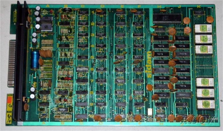
It's a Space Invader clone by Sidam :
https://www.arcade-museum.com/game_detail.php?game_id=13301
http://mamedb.blu-ferret.co.uk/game/invasion/
This guy got one :
http://www.wolfgangrobel.de/arcadereps5/invasion.htm
But unfortunately mine is not exacly like this, the edge connector is different.... Looks like that I have a clone of a clone ?
-
 1
1
-
-
Hello there,
I just got an unknown arcade PCB game, without any text or numbers written on it. There is a 2*22 pin edge connector (key on slot 17). The CPU is a Z80, and there is 7 * 2708 eproms on the left side of the board. On the right side, two 7805, one 7812 and one LM320 (negative voltage regulator).
The datecodes of the ICs are from 79 or earlier. The global aspect of the board let me think that it's from the early 80's.
Thanks to a multimeter, I manage to identify the mains signals on the edge connector :

A "small signal" is an unknown input/output pin, with a small track width (like a joystick input...).
Here is the parts side :

By any chances, can someone recognize this board or the edge pinout ?
I tried to dump the proms, but the 2708 are a bit hard to read (need a ±5V power supply).
Thanks in advance ! ?
-
Sorry I wasn't clear. I suggest that you leave the switch in place (you need it to adjust the volume...) but to avoid potential problems, please don't just "bridge" the two contacts on the switch, make sure to unsolder the power wires from it and link them properly one by one.
I mean, you may not want to have the power going "trough" a partially damaged part... I may be wrong of course, but leaving a power wire connected on a damaged switch may be a source of problems in the future.
-
Nice, thanks ! I'll read through this. ?
-
Yes, but I suggest to remove the switch first !
-
I was willing to post this :
But after reading your post again it seems that it's absolutely not this, sorry.
So this system was able to record on VCR tape the video output of the console ?
-
Hello there,
Maybe someone could be interested by this, or for archival purposes : a system that can record and load a VCS cart on tape. It was published on the February issue (1985) of the magazine "Radio Electronics" :
https://archive.org/details/radio_electronics_1985-02/page/n61/mode/2up
Attached is the PDF article. Looks like that there is a part 1 and 2, but I didn't manage to get the previous issues of the magazine.
The system is based on a Z80 processor. Unfortunately, no eprom code available...
-
I'll try this "unsigned int8_t itoa" function, thanks !!
-
Ill study that, thanks !!
-
Your pictures shows that there is an issue with the Z display axis (the ability of the CRT to "turn on" and "off" the light spot.)
If you are familiar with electronics and if you are aware of the dangerousness of the high voltages inside the Vectrex, the first thing to do should be to test the video outputs of the main logical board (I mean, before the CRT/power board) with a scope, just to locate the problem :on the logical board, or on the CRT power board ?
-
My actual dev enviroment is very light, (Qt creator as IDE, a batch file to compile, and ParaJVE for execution). It works, but it's absolutely not easy to wok with.
I've downloaded Vide, I'll sure take a deep look at it. ?
-
Ok so this actually works :
//* itoa:  convert n to characters in s */

void m_itoa2(unsigned char n, char s[])

{

    unsigned char i, sign,f;


    if ((sign = n) < 0)  /* record sign */

        n = -n;          /* make n positive */


    f=n;


    i = 0;

    do {       /* generate digits in reverse order */

        s[i++] = n % 10 + '0';   /* get next digit */

    } while ((n /= 10) > 0);     /* delete it */


    if (f < 10)

        s[i++] = '0' + n ;


    if (sign < 0)

        s[i++] = '-';

    s[i] = '\0';

    m_reverse(s);

}
It adds a zero in numbers <10.

So yes, maybe it's just a small issue in the ROM code...
-
Many thanks ! It should work perfectly. ?
No, I'll not use the PF for anything else than pure drawing (no collisions checks....).
-
Aouch sorry for being not accurate enough in my description.
My main constraint is to have the multi-sprite kernel. I'll have only one sprite on a scanline at a time, so it should work.
So in this case my only chance to have my two colors background is with a standard playfield ? They say that the PF is mirrored (no so problems here), and that I must use the "playfield" command to draw my background. But I don't know if there is color limitations ?
I'm not yet familiar with the pfheight variable, I'll try that...
Thanks !
-
7 minutes ago, Random Terrain said:
Make sure Load Start Web Page on Open is turned off on the settings page. If you enable it, you'll get a ton of error messages and will probably have to close the program using your computer's Task Manager. Don't try to load any web page with VbB.
Yes I've done that ! I have the web page displayed into Firefox. ?
-
Is it normal that Visual bB needs to be launched in administrator mode ? Sounds strange... ?
(But works perfectly on my Win10 computer)
-
Thanks for the tip, but I didn't manage to make it work.
So if I understand correctly, by setting up the background kernel option it allows me to use the playfield color table to paint the background instead of the playfield blocks.
So I added :
 set kernel multisprite

 set kernel_options pfcolors no_blank_lines background
and
 pfcolors:
   $0E
   $0E
   $0E
   $0E
   $0E
   $B6
   $B6
   $B6
   $F4
   $F4
   $C4
   $0E
end
before my main loop. But there is an error during the assembly :
--- Unresolved Symbol List
pfcolortable             0000 ????         (R )

      2561 bytes of ROM space left
So maybe I'm not filling the data in the good array...?


C64 assembly - simple loop
in Commodore 8-bit Computers
Posted
Works ! Many thanks ! I got it.
By reading the listing output, my string "ALERTE !" is converted into $41 $4c $45 $52 $54 $45 $20 $21
And so I understand why clearing the 6th bit from each byte is giving me back the good character code. (the Hex features of the windows calculator are very helpful 😄)
So far so good, here is what my game looks like now :
Two moving sprites on the top, one moving player at the bottom (driven by the keyboard) and the player can shoot a weapon (no collision detection for now). I used two tables to display the background (one for char codes, one for the color codes). Maybe a bit heavy but it works.
Of course it will not be THE game of the year, but it's a way for me to learn assembly language !!