


yorgle
-
Posts
596 -
Joined
-
Last visited
Content Type
Profiles
Forums
Blogs
Gallery
Events
Store
Posts posted by yorgle
-
-
Thanks for the input, Robert. It just so happens that a hagstrom is what I'm using right now ( the LP-24version). I must say that it works great--except it has to be hardwired into the matrix and cannot be physically connected to both the atari and PC at the same time. If I can figure out Candle's idea, I think it it might play well with both systems and would not require significant modifications to the keyboard. But first I have to get it to be recognized by my PC. It seems like no matter what driver I try, windows refuses to talk to it.
-
Apparently, I'm the only one really interested in this, but for what it's worth, I'll keep posting what limited progress I make, if for no other purpose than to entertain you guys. The first issue I ran into was a bizarre rapidly alternating connect/disconnect cycle when I plugged the device into my Windows 10 pc. Adding a dedicated +5vdc power supply to the circuit fixed that and at least it now shows up in Device Manager, albeit as an "Unknown USB device" with the dreaded "device descriptor failed" error.
-
 2
2
-
-
Any chance of incorporating the ps2 output idea in this revision?
-
Something is still not right as my pc won't recognize the circuit. I've checked, double and triple re-checked my circuit to be sure it is identical to Candle's schematic. I programmed the Atmega using the hex file in Candle's first post, and my programmer says the write was successful and verifies it so there must be a step to this project that I'm missing. A special driver on the PC side? Any hints or suggestions to point me in the right direction will be greatly appreciated.
-
I agree that the benefit of most hardware upgrades isn't much without software, but for me, upgrading my 1200 hardware is a great way to learn and appreciate the knowledge and talents of the designers-- of both the old stuff as well as the new stuff.
-
3
-
-
I decided to rebuild the circuit on a larger breadboard for testing- here's the rats nest in all its glory. Just about everything except the crystal and the diodes was scrounged from my junk parts drawer
 I still need to find something to use for the keyboard connector header pins. But I want to get the Atmega programmed first.
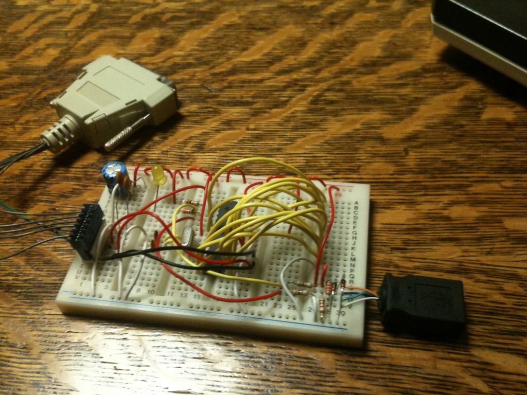
I found this super-simple avr programmer circuit that uses only a parallel port connector and a few resistors: http://nahians-avr.webs.com/parallelportprogrammer.htm It seems too good to be true (it took less than 2 minutes to build) but I'm not quite sure how power is supposed to get to the Atmega for programming. Perhaps the usb needs to be connected while programming? Any thoughts or suggestions will be most welcome.
-
4
-
-
A few years back I was buying a lot of 8-bit stuff and in my pile of cables, I found this:
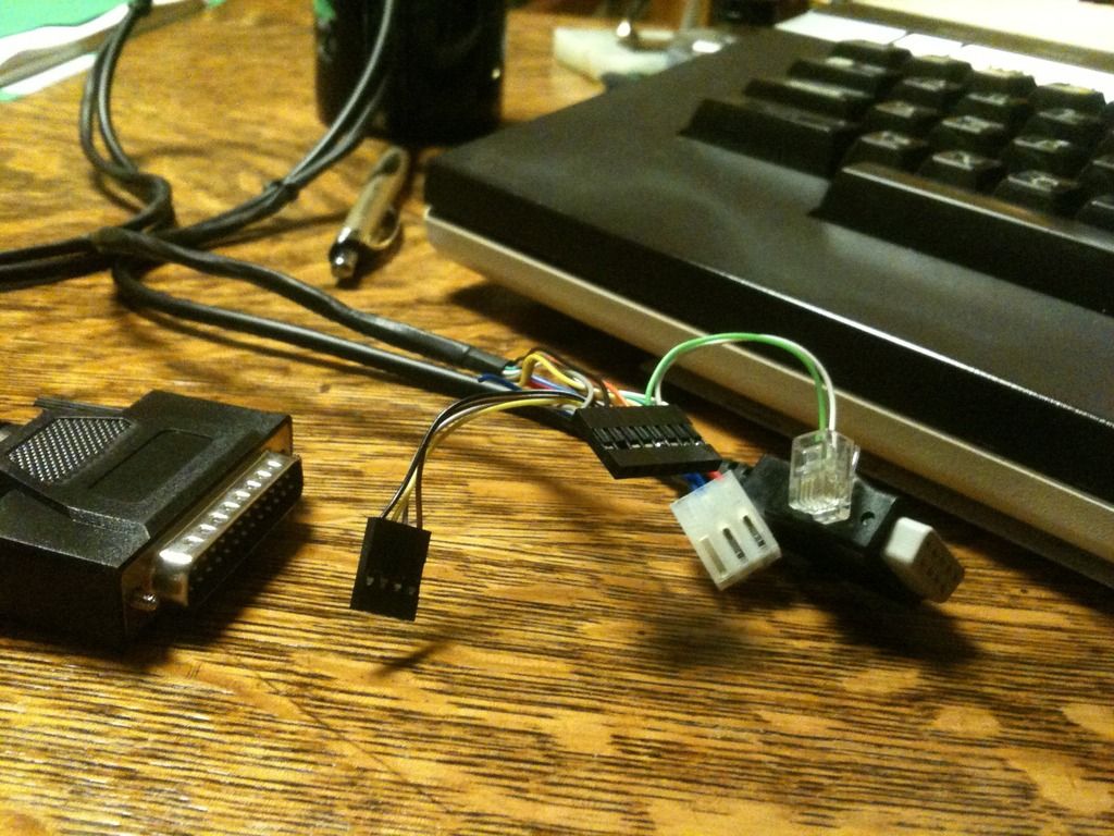
It has a parallel port connector at one end, with two cables running from it- one to a female atari joystick port connector and the other to a bunch of header connectors- even a telephone jack. For the life of me, I can't recall what this was supposed to be used for. Does anyone here recognize it?
-
I don't suppose there's any chance at ordering one now, is there?
-
Ok, I give up. With the 4051s inhibited, (triggered by power from the ps/2 connector) the encoder works as it should, but the shared ground that is needed to switch the inhibit pins from high to low and vice versa apparently prevents the keyboard from working with the Atari. The Trans-key II option is looking better and better.
-
For the F1-F4 keys, how about using the inverse key with the number keys to simulate the PC function keys, e.g., Inv+1=F1, Inv+2=F2, and so on. That would give you at least the first ten. Then maybe Inv+ the AtariF1, F2, etc. would give you the PC version of F11-F14.
-
Key mapping is not too critical because it can always be rearranged with software at the PC side.
-
Obviously, using the Atari keyboard means giving up a lot of key functions. 99% of my use is creating/editing documents so I don't really need that many keys. I have an Atari numerical keypad to help out. Right now, I have the F1-F4 keys mapped to cursor duty just like stock. The BREAK key is my close window key. The Inverse key is ALT and Help is Line end. Before adding on my switching circuit, RESET was mapped to ctl-alt-del, START pulled up the Windows start menu, OPTION was the Windows key and SELECT was select-all.
-
After messing with my circuit further, I realized that the Hagstrom encoder is the problem, not the shared ground. The firmware can't recognize a ground as an input so I'm dead in the water. I'm going to contact Hagstrom to see if there's a way to reprogram it to get around this limitation. Again, this only affects the four GTIA keys so it's not really that big of a deal except that it would be nice to have the extra functions.
-
Michael- thank you SO MUCH for posting your thought process on this project.
-
Ok, not so fast... it seems I've got an issue with my circuit that only affects the GTIA lines (Reset, Start, Select and Option). In order to pull the inhibit pins on the 4051's high, the keyboard has to share a ground with the ps/2 encoder. While that doesn't bother the encoder as far as matrixed inputs are concerned, apparently the encoder can't deal with the shared ground as input. I think the only way to address that would be to physically break the traces on the keyboard PCB so they can be switched on/off or otherwise isolated. I hate to lose 4 keys, but I really don't want to get into that much physical modification. The TransKey solution is looking better and better.
-
Measured at the apprropriate pins at the connector, I would expect that resistance should be at or near zero ohms when the keys are pressed. The pads on the mylar can be stubborn. I've had good luck cleaning them with a pencil eraser. Another trick I've learned is to put a strip of tape over the top of the Mylar where the lines connect to the pcb so when the plastic key assembly is screwed on the little bit of extra thickness sandwiches the connector together with a bit more force.
-
1
-
-
Use a short bit of wire to momentarily jump pin 14 with pin 11,12 or13 at the keyboard connector. That will tell you if it's the keyboard or not.
-
1
-
-
Well, I tested my switching circuit today and I think it's going to work. I've verified that using the 4053 to trip the keyboard 4051s into inhibit mode, eliminates interference with the PC encoder. Now I need to figure out a clean way to connect the circuit into the four GTIA lines. For testing, I just bent the four pins upward slightly so they don't slide into the connector and temporarily soldered my leads directly to the pins. The wires from the other side of the switch are just pushed into the Leyboard connector.
-
ME WANT!!!
 I'm afraid I can't be of much help as far as coding, but if you need any testing done, I've got a pile of 1200xl's sitting here.
 -
If you dont mind elaborating on that idea, I'm curious what would this physically look like? From your description, I'm picturing an 8 wire ribbon cable running from the keyboard connector to a board with a processor chip and a ps2 connector. If so, that would definitely be a cleaner and less solder intensive install than my setup.
-
Yes. Each row and column is hard wired to the encoder. And because it's programmable, any PC function can be assigned to any Atari key. It's complicated, but it works. If I had the skills, I'd prefer to build/code a translator that could read the Atari key codes at, say, a joystick port and convert that to PC keyboard codes. The downside to that, however, would be that the Atari would have to be powered on all the time.
-
I use my 1200xl as my pc keyboard at my office. It looks great on my desk and can't be best for typing. However, my present interface doesn't work unless the keyboard is physically disconnected from the 1200 motherboard.
-
I harvested a couple of 4053's from an old telephone at my office and came up with a circuit: use the 3 switches from the 1st 4053 and 1 from the second 4053 to toggle the RESET, START, SELECT and OPTION pins at the Atari connector whenever a +5v signal from the encoder is present at the common pins for each of those switches. I can use that same +5v signal to flip the remaining 2 switches of the second 4053, pulling the inhibit pins of each 4051 on the Atari hi whenever the encoder is on and lo when it is off. Everything is soldered up on a protoboard and ready to install, but I have one final question regarding the 4053's: with four of the switches only being used SPST, should I connect the unused second throw pins for these switches to an led or something so the switches don't float?
-
I see what you mean. The encoder does its own scan, reading the rows and columns at the respective pins of the 4051's. When it senses a contact between a row and a column, i.e., a keypress, it converts that to a PC recognizable key code and sends it to my PC via ps/2.

Atari keyboard to USB
in Atari 8-Bit Computers
Posted
Ok, some progress... I got the LED to blink when I press keys. It's man vs machine now and I'm determined to figure this out!