Jump to content
  • entries
    8
  • comments
    4
  • views
    5,527

Making an Editor for 7800 ASM Tools


Z80GUY

972 views

Well I decided to try my hand at writing assembly for the 7800 (every ones gotta do something right ?).


I looked through the forum and found all the tools and docs I would ever need, as I was searching I found that the 2600 forum had a shed load of tools tied together from a member written IDE and I thought hmm why don't the 7800 folks got something like that ?.


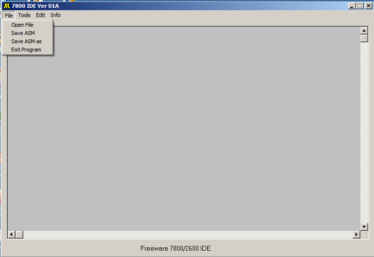
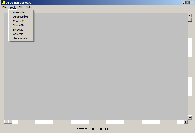
So I decided to write one that would tie all the command line tools together in one IDE, so say if you wanted to view a disassembled ROM file you could go to tools and select Disasm and select the BIN file and the Distella tool would do its thing and the IDE could open it and display it in the editor window for you or in a seprate window from the editor.


I know that this is not needed but I felt that since I am basicly a lazy person I would like a tool to interface with all the commandline stuff for me. :)


Editor1pic.png

editor2pic.png

editor3.png

editor4.png


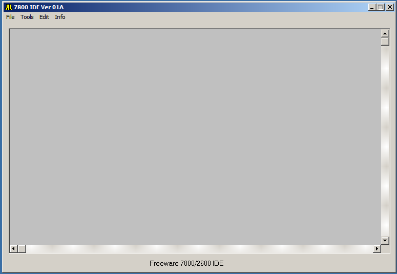
This is just a rough draft of the IDE I am making, for the moment it is not usable but in a couple of weeks it should be ready for normal usage.


Things to do are:


1. build a help file system with all 7800 tech docs accessible from the editor


2. add a HEX converter to the interface (kinda like SIDE Kick)


3. add a couple of user assignable slots for external programs


4. get permission from the various tool owners to package the IDE and tools together in an installer

to help new programmers out with a single download from one spot instead of several spots.

that way it will be like a community DEV kit complete with Tools and Docs.


So in the comming days I will post pics and give updates as I go, I welcome all comments and suggestions good or bad makes no diffrence to me.


Carl.

3 Comments


Recommended Comments

YES!!!! Looking forward to this :)


I am still working on it almost done, but my real world job keeps getting in the way :ponder: so far I have gotten firm understanding of the 6502, now just have to get a better understanding of Maria and Display Lists that she uses.


Carl

Link to comment

90% of what everyone knows about MARIA is from the 7800 SOFTWARE GUIDE. However, here's an extract of some stuff I wrote for the 7800 Programming Wiki (RIP):


An overview of how the 7800 produces graphics. On the 7800 a "display list list" contains a series of 3 byte entries which contain the address of a "display list" and the number of scanlines (typically 8 or 16) to draw using the display list. Each "display list" contains a series of 4 or 5 byte entries which contain the base address of a sprite or a character map along with the palette to use for the sprite/characters, the number of bytes, and the horizontal position.


MARIA has the ability to cause an NMI when it completes a DLL entry ("display list interrupt").


The different 7800 graphics modes are defined outside of the display list by a combination of the MARIA CTRL register (horizontal resolution) and a flag in a 5 byte display list entry (colors per sprite).


On the 7800 the screen is broken up into "zones" of 1-16 scanlines (typically 8 or 16), based on the 3 byte DLL header. The DLL header contains a 16 bit address pointer to the display list for the zone.


The display list is made up of a sequence of 4 or 5 byte sprite headers ended by a 2 byte null header. Each direct sprite header contains a 16 bit address pointer to the graphics data drawn on the last scanline of the zone. (Indirect sprites, or tiles, are a little different.)


Graphics data is laid out "upside down" with the last scanline on the lowest address and each scanline on a separate page. e.g. for a 2 byte x 16 line sprite

$e000-$e001 bottom line 
$e100-$e101 2nd last line 
... 
$ee00-$ee01 2nd line 
$ef00-$ef01 top line

Horizontal motion on the 7800 is easy 'cause each sprite header contains a 1 byte horizontal position (though this means only 160 onscreen positions even in 320 modes). Vertical motion requires a little more work. Assume we are using 16 line sprites and zones. If the sprite is "on grid" then we have the following

line 0-15 DLL -> sprite header -> $e000


Now say that the sprite moves down one scanline, then the sprite is overlaps two zones and we need the following

line 0-15 DLL -> sprite header -> $e100

line 16-31 DLL -> sprite header -> $d100


Some of this seems counter-intuitive, but remember that the sprite header points to the bottom of the sprite. So the top scanline of the second zone will draw the graphics stored at $d100 + 15*256 = $e000 or the last scanline of the sprite. So the sprite has moved down one scanline.


This is also where "Holey DMA" comes into play. In the above example the top scanline of the first zone will draw the graphics stored at $e100 + 15*256 = $f000. In the DLL there are two flags, one which treats odd 4K segment of ROM as full of zeros. So when that flag is set, graphics reads from $dxxx and $fxxx will be treated as zeros. Thus we can store code and non-graphics data in those segments.

Link to comment
Guest
Add a comment...

×   Pasted as rich text.   Paste as plain text instead

  Only 75 emoji are allowed.

×   Your link has been automatically embedded.   Display as a link instead

×   Your previous content has been restored.   Clear editor

×   You cannot paste images directly. Upload or insert images from URL.

Loading...
  • Recently Browsing   0 members

    • No registered users viewing this page.
×
×
  • Create New...